

Product Overview & Sourcing Context
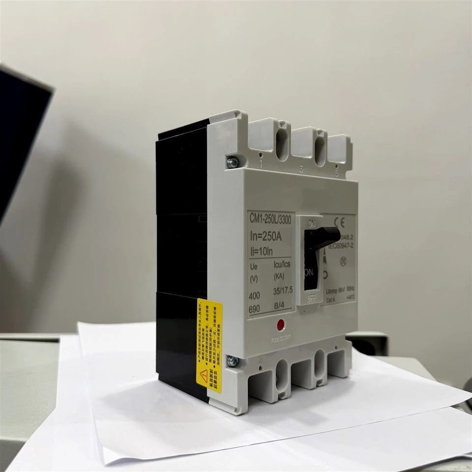
A Molded Case Circuit Breaker (MCCB) is an essential low-voltage electrical protection device engineered to automatically interrupt fault currents under specified overload and short-circuit conditions. It safeguards low-voltage power distribution networks and downstream industrial assets against catastrophic electrical failures.
For professional electrical panel builders, industrial equipment original equipment manufacturers (OEMs), system integrators, and electrical distributors, effective MCCB selection extends beyond matching rated current. Engineering validation must account for rated operational voltage, ultimate and service short-circuit breaking capacities, pole configurations, trip unit characteristics, and physical panel mounting constraints.
-
![High Quality MCB Residual Current Circuit Breaker]() High Quality MCB Residual Current Circuit BreakerBrand: QHECOview more
Rated Voltage: 230V
Breaking Capacity: 32A
Place of Origin: Zhejiang, China
Rated Frequency (Hz): 50Hz -
![MCB Transparent Circuit Breaker]() MCB Transparent Circuit BreakerBrand: QHECOview more
Rated Voltage: 230/400V
Breaking Capacity: 32/4000A
Place of Origin: Zhejiang, China
Rated Frequency (Hz): 50Hz -
![MCB 3-Pole Circuit Breaker]() MCB 3-Pole Circuit BreakerBrand: QHECOview more
Rated Voltage: 230/400V
Breaking Capacity: 63/4000A
Place of Origin: Zhejiang, China
Rated Frequency (Hz): 50Hz -
![MCB Miniature Circuit Breaker]() MCB Miniature Circuit BreakerBrand: QHECOview more
Rated Voltage: 230V
Breaking Capacity: 32A
Place of Origin: Zhejiang, China
Rated Frequency (Hz): 50Hz -
![MCB Residual Current Breaker Transparent]() MCB Residual Current Breaker TransparentBrand: QHECO Rated Voltage: 230/400V Breaking Capacity: 32A Place of Origin: Zhejiang, China Rated Frequency (Hz): 50Hzview more


Construction and Operating Principle
An industrial MCCB integrates a reinforced housing, high-conductivity current paths, a quick-make/quick-break operating mechanism, a precision trip unit, and an arc-extinguishing chamber.
Insulating Housing: Compression-molded from flame-retardant, glass-fiber reinforced thermoset polyester composite. It delivers high dielectric breakdown strength, an IK07 mechanical impact resistance rating, and UL 94 V-0 flammability compliance.
Current-Carrying Contacts: Incorporates silver-tungsten (AgW) alloy contact tips welded onto electrolytic copper bridges. This alloy combination minimizes electrical contact resistance and resists arc erosion during high-fault interruptions.
Arc-Extinguishing Assembly: Features a multi-plate de-ion grid constructed from ceramic-insulated cold-rolled steel plates, designed to rapidly split, cool, and extinguish electrical arcs within milliseconds.
Operating Mechanism and Trip Unit: Employs a spring-loaded, trip-free toggle mechanism independent of manual handle actuation speed, ensuring fault clearance even if the handle is physically blocked. Thermal-magnetic or electronic trip units monitor line conditions and initiate immediate fault isolation.
Technical Specifications & Selection Parameters
|
Parameter |
Specification & Verification Requirement |
|
Product Type |
Molded Case Circuit Breaker (MCCB) |
|
Rated Current (In) |
100A, 250A, 400A, 630A, 800A (Confirm model availability) |
|
Number of Poles |
3P / 4P (Verify neutral pole protection arrangement) |
|
Rated Operational Voltage (Ue) |
415V / 690V AC, 50/60Hz |
|
Rated Insulation Voltage (Ui) |
800V AC |
|
Ultimate Short-Circuit Breaking Capacity (Icu) |
35kA - 65kA at 415V AC (Model-dependent, verify datasheet) |
|
Service Short-Circuit Breaking Capacity (Ics) |
50% to 100% of Icu |
|
Trip Unit Type |
Adjustable Thermal-Magnetic or Electronic Trip Unit |
|
Mechanical / Electrical Endurance |
Mechanical: 10,000 cycles; Electrical: 3,000 cycles |
|
Protection Degree |
IP20 (Terminal blocks), IP40 (Front escutcheon with door cutout) |
|
Compliance Standards |
IEC 60947-2, CE, RoHS |
Critical Engineering Parameters for Selection
Rated Current & Load Matching
Must align with conductor ampacity, system load profiles, and panel thermal management limits.
Operational Voltage vs. Breaking Capacity
Short-circuit breaking ratings (Icu and Ics) must be evaluated at the actual system operating voltage rather than extrapolated from generalized ratings.
Selectivity & Coordination
Thermal overload pickup (Ir) and magnetic instantaneous thresholds (Ii) must coordinate seamlessly with upstream and downstream protective devices.
Industrial reliability is anchored in rigorous factory testing and tight manufacturing tolerances:
Precision Stamping & Molding: Enclosure components maintain critical dimensions within ±0.1mm tolerances via automated compression presses. Current paths are fabricated from 99.9% pure electrolytic copper to optimize electrical conductivity and minimize internal heat rise.
Automated Calibration & Trip Testing: Every assembled circuit breaker undergoes automated calibration on a current injection test bench to verify bimetal thermal deflection curves and electromagnetic instant-trip thresholds against strict compliance tolerances.
Dielectric Withstand Verification: Routine factory testing applies a 2500V AC dielectric strength test between live electrical parts and the earthed frame for 60 seconds to ensure absolute insulation integrity prior to packaging.
Mechanical Endurance Verification: Regular production sampling undergoes mechanical toggle testing up to 10,000 cycles to verify latching reliability and spring fatigue resistance.
Typical Applications
MCCBs are deployed across professional electrical distribution environments where technical ratings and system compatibility have been verified:
Industrial Switchgear
Main and sub-distribution protection in heavy manufacturing plants and machinery power feeds.
01
Motor Control Centers (MCC)
Feeder and branch circuit protection for industrial motor loads.
02
Commercial Building Distribution
Main switchboards and floor distribution panels in large commercial facilities.
03
Specialized Infrastructure
Data center power distribution units (PDU) and industrial automation control enclosures.
04
As one of the most experienced circuit breaker manufacturers in China, we also support customized service. We warmly welcome you to buy durable circuit breaker for sale here from our factory. If you have any enquiry about cooperation, please feel free to email us.
circuit breaker for


