

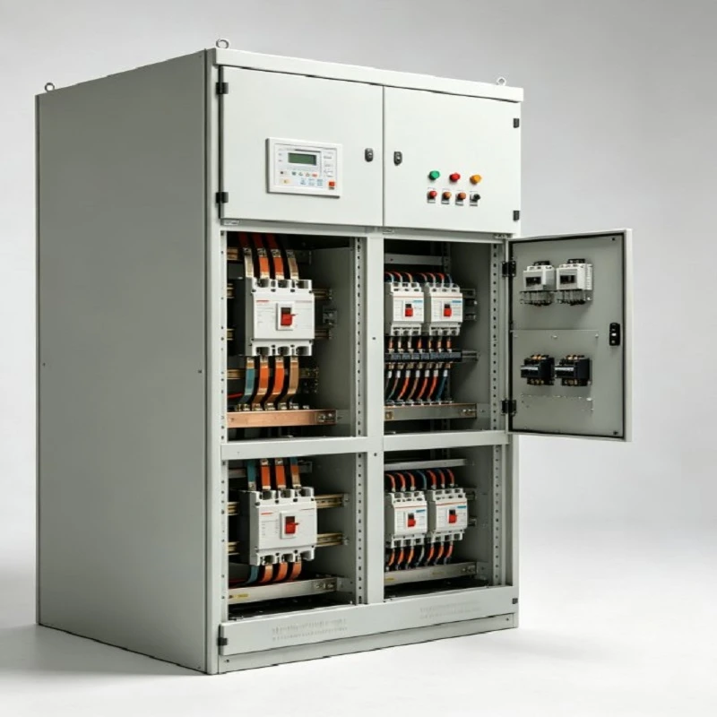
A Multi-Feeder Main Switchboard is a floor-standing low-voltage assembly that receives power from one incoming source and distributes it through multiple independently protected feeder circuits. The assembly brings together the incoming section, main copper busbar, feeder compartments, cable termination areas, metering provisions and control wiring.
The feeder layout follows the electrical load schedule, single-line diagram, cable requirements and available installation space. Different feeder ratings can be arranged within the same switchboard, allowing separate load groups to be supplied from one main distribution point.
Main Configuration
Incoming Section
The incoming section contains the main switching and protection device, incoming cable termination and associated metering or control components. The compartment size follows the incoming current and cable arrangement.
Main Busbar
Copper busbars distribute power from the incoming section to the outgoing feeders. Busbar cross-section and arrangement are matched to the rated current and required short-circuit withstand level.
Feeder Sections
Each feeder has its own protection and cable connection position. Feeder ratings can vary according to the connected load and electrical design.
Cable Compartment
Cable compartments provide space for conductor routing and termination. Entry direction, cable quantity, conductor size and bending space are considered during layout preparation.
Technical Parameters
|
Parameter |
Typical Value |
|
Rated Voltage |
400 V AC |
|
Maximum Rated Voltage |
690 V AC |
|
Frequency |
50 / 60 Hz |
|
Main Rated Current |
400–4000 A |
|
Feeder Rated Current |
16–1600 A |
|
Number of Feeders |
4–20 |
|
Short-Circuit Withstand |
Up to 50 kA |
|
Main Busbar |
Copper |
|
Busbar Rated Current |
Up to 4000 A |
|
Enclosure Material |
Steel |
|
Protection Degree |
IP31–IP54 |
|
Cable Entry |
Top / Bottom |
|
Installation |
Floor-standing |
|
Control Voltage |
24 V DC / 110 V AC / 230 V AC |
|
Metering |
Optional |
Feeder Arrangement
Separate Load Groups
Individual feeders supply defined downstream circuits such as production equipment, building services, distribution boards or auxiliary systems. Each circuit has its own rated current and protection requirement.
Mixed Ratings
A switchboard can combine different feeder ratings within one lineup. This allows the feeder schedule to follow the actual load requirements rather than using one common rating.
Spare Positions
Unused feeder positions can be reserved when future circuit additions are included in the project plan. The number of spare ways is defined during engineering review.
Protection and Control
Main Protection
The incoming protective device is selected from the system voltage, rated current and available short-circuit level. Its position is coordinated with the incoming cable and main busbar.
Feeder Protection
Each outgoing feeder uses a protection arrangement matched to its rated current and connected load. Device dimensions, connection points and cable access are included in the compartment layout.
Metering
Voltage, current and energy measurement provisions can be incorporated where required by the electrical specification. Metering positions are arranged for clear identification and access.
Mechanical Construction
Steel Enclosure
The cabinet structure uses fabricated steel sections with dedicated areas for electrical devices, busbars and cable termination.
Internal Arrangement
Equipment positions are coordinated with electrical clearances, cable routing, busbar access and operating space. The general arrangement is reviewed before fabrication.
Cable Access
Top or bottom cable entry can be selected according to the installation layout. Cable compartment dimensions are checked against conductor size, quantity and termination requirements.
Manufacturing and Quality Control
Engineering Review
The single-line diagram, feeder schedule, rated current, short-circuit requirement, cable information and cabinet dimensions are reviewed before production. The approved layout becomes the basis for fabrication and assembly.
Busbar Processing
Copper busbars are measured, cut, drilled, formed and assembled according to the approved arrangement. Connection positions are checked against the incoming and feeder sections.
Final Inspection
Inspection covers cabinet dimensions, component identification, busbar connections, internal wiring, protective clearances and feeder positions. Electrical checks follow the applicable project inspection requirements.
Application Selection
Manufacturing Facilities
Separate feeders can supply production lines, machinery, process systems and auxiliary loads from a centralized low-voltage distribution point.
Commercial Buildings
Feeder circuits can serve downstream distribution boards, mechanical services, lighting systems and major electrical loads.
Warehouses
Dedicated circuits can be allocated to material-handling equipment, HVAC systems, lighting and other defined facility loads.
Infrastructure Facilities
The multi-feeder arrangement suits centralized distribution rooms where several downstream circuits require individual protection and controlled cable termination.
Procurement Information
Electrical Data
Provide rated voltage, frequency, phase arrangement, incoming current and short-circuit level.
Feeder Schedule
List every feeder with its rated current, protection requirement, cable size and cable quantity.
Mechanical Data
Confirm cabinet dimensions, installation space, cable entry direction, access requirements and site conditions.
Project Documents
A single-line diagram, load schedule and general arrangement drawing provide the main reference for technical review, layout confirmation and quotation.
FAQ
Q: What is a Multi-Feeder Main Switchboard?
A: It is a low-voltage main distribution assembly that receives incoming power and distributes it through multiple individually protected feeder circuits.
Q: How many feeders can be included?
A: A typical configuration may contain 4–20 feeder positions. The final quantity depends on feeder ratings, device dimensions, busbar capacity, cable space and cabinet dimensions.
Q: Can different feeder ratings be combined?
A: Yes. Individual feeder ratings can be selected according to the load schedule, cable requirements and protection arrangement.
Q: What voltage and current ranges are available?
A: Typical configurations use 400 V AC systems, with assemblies available up to 690 V AC and main current ratings up to 4000 A, subject to the specified electrical design.
Q: What information is needed for quotation?
A: The single-line diagram, incoming rating, short-circuit level, feeder schedule, cable information, cabinet dimensions and metering requirements provide the main technical basis.
Q: Can cable entry be specified?
A: Yes. Top or bottom entry can be selected according to the electrical room layout, cable routing and termination arrangement.
Hot Tags: multi-feeder main switchboard, China multi-feeder main switchboard manufacturers, factory, Motor Control Center Cabinets


