

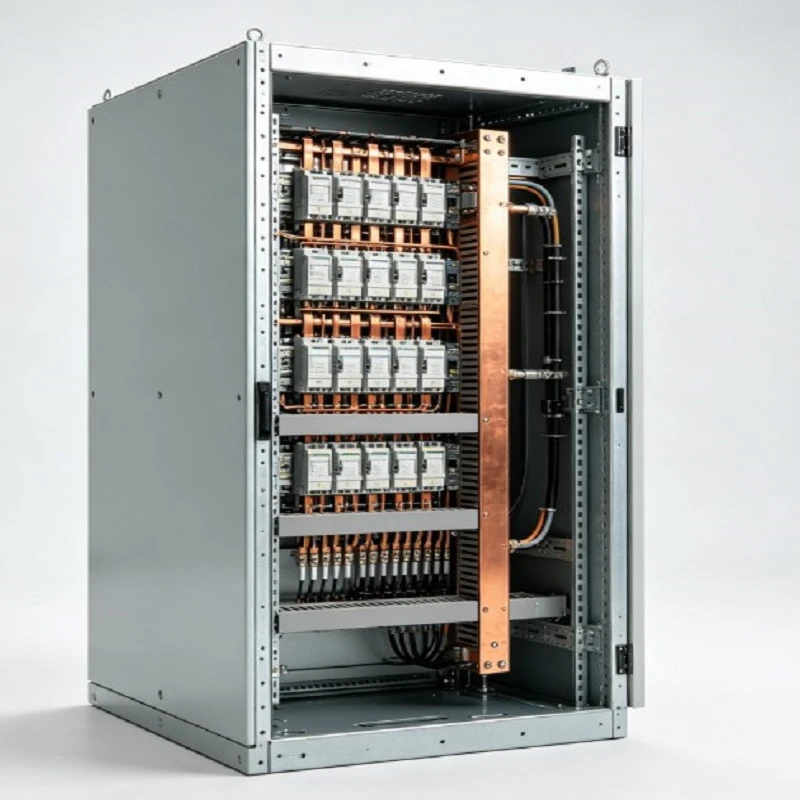
An Industrial Main Distribution Switchboard receives low-voltage incoming power and distributes it through multiple protected feeder circuits. The assembly integrates the incomer section, copper busbar system, feeder compartments, cable termination areas, metering positions and control wiring in a floor-standing enclosure.
Typical systems operate at 400–415 V AC and 50 or 60 Hz, with main current ratings commonly selected from 400 A to 6300 A. The final configuration is established from the single-line diagram, load schedule, fault level, feeder requirements and installation conditions.
Main Configuration
Incomer Section
The incomer houses the main switching and protection device, incoming cable connections and the required measurement or control interfaces.
Copper Busbar
Copper main and distribution busbars transfer incoming power to the feeder sections. The busbar rating is selected according to the required continuous current and assembly configuration.
Feeder Sections
Each feeder section provides a defined circuit path for downstream loads. Feeder ratings and compartment allocation are selected from the project load schedule.
Cable Compartment
Termination areas provide working space for incoming and outgoing cables. Entry can be arranged from the top or bottom according to the installation layout.
Key Technical Parameters
|
Parameter |
Typical Range / Value |
|
System voltage |
400–415 V AC |
|
Frequency |
50 / 60 Hz |
|
Main rated current |
400–6300 A |
|
Busbar rated current |
400–6300 A |
|
Short-circuit withstand |
Up to 100 kA |
|
Enclosure protection |
IP31–IP54 |
|
Installation |
Floor-standing |
|
Cable entry |
Top or bottom |
|
Outgoing feeders |
4–36 circuits |
|
Ambient temperature |
-5°C to +40°C |
|
Internal separation |
Form 1–Form 4 |
Selection Criteria
Rated Current
The main rating is selected from the calculated incoming load and expected operating demand. Feeder ratings are determined separately from the connected loads and cable requirements.
Short-Circuit Level
The assembly short-circuit withstand rating should correspond to the calculated fault level at the installation point. This value affects busbar design and internal construction.
Feeder Layout
Feeder quantity, circuit ratings and protection arrangements determine the number of functional sections and the available termination space.
Enclosure Protection
IP protection is selected according to the installation environment and required protection against solid objects and water ingress.
Typical Applications
Manufacturing Plants
Used for centralized distribution to production machinery, motors, process equipment and downstream distribution panels.
Industrial Buildings
Installed in main electrical rooms to distribute incoming low-voltage power across defined load groups.
Production Lines
Separate feeder circuits can supply production equipment, auxiliary systems and local distribution panels from one main assembly.
Infrastructure Facilities
Suitable for facilities where incoming supply, feeder capacity, cable routing and electrical-room dimensions are established during project design.
Protection and Monitoring
Main Protection
The incomer protection rating is selected according to the incoming supply, rated current and calculated fault conditions.
Feeder Protection
Each outgoing circuit can have an independently specified protection rating based on its connected load and cable capacity.
Metering
Metering sections can be allocated for incoming or selected feeder circuits. Measurement requirements are defined according to the project monitoring scheme.
Interlocking
Electrical or mechanical interlocking can be incorporated where the switching sequence requires controlled operation between designated circuits.
Manufacturing and Assembly
Enclosure Fabrication
Sheet metal sections are processed to the specified cabinet dimensions, compartment arrangement, access requirements and cable entry positions.
Busbar Processing
Copper bars are cut, drilled, formed and assembled according to the approved current rating and connection arrangement.
Internal Wiring
Protection devices, terminals, control circuits and identification points are installed according to the approved electrical drawings.
Assembly Inspection
Checks cover component position, wiring continuity, terminal identification, mechanical connections and configuration against the approved documents.
Technical Documentation
Single-Line Diagram
The SLD identifies the incoming source, main busbar, feeder circuits and principal protection arrangement.
General Arrangement
The GA drawing defines cabinet dimensions, section allocation, cable entry positions and installation interfaces.
Component Schedule
The schedule identifies the principal switching, protection, metering and control components together with their specified ratings.
Inspection Records
Inspection records document the agreed production checks and provide supporting information for project acceptance.
Project Configuration
Electrical Data
Provide system voltage, frequency, incoming current, short-circuit level and the complete feeder schedule for technical configuration.
Physical Data
Cabinet dimensions, available installation space, cable entry direction, access clearance and cable termination requirements determine the enclosure arrangement.
Final Review
Before production, the electrical ratings, feeder list, busbar arrangement, protection functions, dimensions and cable interfaces are checked against the approved project documents.
FAQ
Q: What is an Industrial Main Distribution Switchboard used for?
A: It receives incoming low-voltage power and distributes it to multiple protected downstream circuits within an industrial electrical distribution system.
Q: What voltage and current ratings are available?
A: Typical configurations cover 400–415 V AC systems with main current ratings from 400 A to 6300 A. The required rating is selected from the project electrical design.
Q: How is the short-circuit rating determined?
A: The required withstand level is based on the calculated fault current at the installation point and the specified electrical system conditions.
Q: Can the feeder quantity and layout be customized?
A: Yes. Feeder quantity, circuit ratings, compartment allocation, cable termination and metering positions can be arranged according to the approved project requirements.
Q: What documents are needed to start a quotation?
A: A single-line diagram, load or feeder schedule, system voltage, incoming current, short-circuit level, cable information, required IP rating, cable entry direction and available installation space provide the main technical input.
Hot Tags: industrial main distribution switchboard, China industrial main distribution switchboard manufacturers, factory, Motor Control Center Cabinets


